What is the Roll Forming Process?-metal roofing machine
What is the Roll Forming Process?
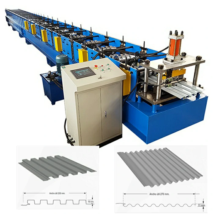
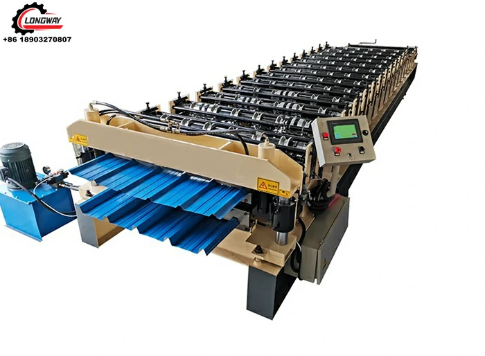
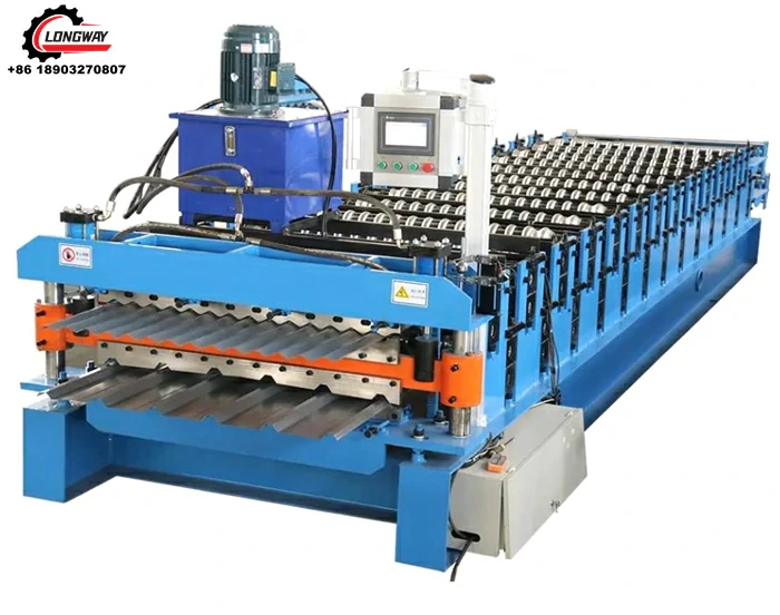
If sheet metal fabrication and aluminum extruding got together and had a baby, you’d get roll forming. Roll forming is like sheet metal fabrication where thin flat sheets of metal are bent into a 3D shape, but in contrast, these bends are formed gradually and continuously so a constant 2D cross-sectional shape comes out the other end like an extrusion. Long strips or coils of flat metal are fed into one end of a roll forming line where it passes through a series of rolling dies and comes out the end in a totally new shape.
For the most part, other processes can be used to make the same parts that are achieved by roll forming. If very long lengths or high volumes are needed though, roll forming offers distinct economic advantages and comes with great dimensional reliability as well.
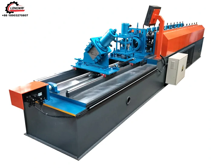
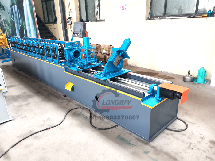
Light steel ceiling CU channel roll forming machine
Where Have You Seen These Parts?
Roll-formed parts are common in building construction. Steel buildings like pole barns, aircraft hangars, or other modern commercial construction show off a lot of examples. The door frames, wall studs, exterior sheathing, roof panels, and flashing are all roll-formed. Even residential seamless gutters that are made on-site in front of your house out of a trailer utilize a small roll forming machine.
 Photo Courtesy of Walters Buildings
You’ll find these parts all over automotive builds too in decorative trim on the surface, structural framing members within, and other components in between.
So, you think you need a roll-formed part. Where do you begin?
The part concept must be consistent and must be in high demand. Roll forming is a process requiring a lot of machine setup investment for a production run. The parts to be formed will need to account for the cost of this setup, so it’s better if the quantity to be produced is very high. Once the machine is dialed in, you won’t want to be making adjustments for multiple sizes or versions of the part during the run. If your concept is high volume in one profile, move on to defining the shape.

Conceptually, your part shape has to be definable by a 2D profile drawn by a line of uniform thickness. An industrial designer can take the needs of the application into account and with some rough calculations, start with a nominal idea of material type and thickness. This will give the designer a more accurate idea of concept limitations in shaping the part for the intended purpose. Certain features like closed profiles and deep, narrow folds will be avoided and symmetry will be sought where possible. As with extrusions, a cross-sectional arrangement of mating parts or surfaces might serve as a good baseline around which to draw the roll-formed part.
The resulting concept shape will be a line that traces the finished bent profile and an idea of the stock material to be used. If you were to grasp each end of that line and stretch it taught like a string in a straight line between your fingers, you’d have the raw material width. This now gives you a fairly accurate idea of the production part costs right away.
What is the Engineering Process for Roll Forming?
Once the concept has been defined by an industrial designer and volume/cost estimates validated for the application, design engineers will work the part design into its final specifications for manufacturing. Many of the same manufacturing considerations as with aluminum extrusions and sheet metal processes apply here. Like aluminum extrusions, roll-formed metal designs will ideally have some general symmetry. This is not critical but does aid in the shape carrying straight through the roll forming line. Also, deep sharp or narrow features should be avoided. Forming these would require relatively thin roller dies. These can be prone to breakage in heavier gauge materials. Akin to sheet metal fabrication on a press brake, roll forming must allow a minimum bend radius for the material to form around the die. Also like press brake forming, tooling must be able to engage with the material on multiple sides in order to create a reliable shape. This means that a bend can’t be defined too close to the edge of the material because it needs enough of a leg to engage with the roller die on the backside of the bend. This also means that hollows are strongly discouraged. Hollow sections require a bend to be made without a tool on both sides of the material. It’s just open air on one side, so it’s called “air bending”. Variations in the material’s composition or temperature can result in much wider dimensional tolerances. While not strictly forbidden, air bending is certainly frowned upon if it can be avoided.

What Materials are needed for Roll Forming?
Roll forming is most typically done with coiled low carbon steel of various gauges. Stainless steels of various alloys (300-series, or 400-series), aluminum, or copper are also used. This latter group already inherently has at least some corrosion resistance, though some surface treatments can be applied to materials before forming, adding to manufacturing process efficiencies. This includes pre-painted, galvanized, annealed, or plastic-clad materials. Many of these will work well on lighter gauge cosmetic purposes. Sharp bends and heavy gauge materials will stretch, microfracture, and expose the raw material beneath the surface, which negates the corrosion protection properties. Also, any sort of pierce, punch, notch, or end cuts of the material will expose the raw material cross-section to the elements. Experienced engineers will know the restrictions in minimum bending radii for various material/finish combinations.
What is the Structural Analysis for Roll Forming?
Structural analysis is common to many roll form parts in beam loading. For relatively simple load characteristics with regular or no punched, notched or formed features, engineers will perform beam loading calculations using properties from the final cross-sectional profile and material with the designed loading parameters. These calculations are very reliable and can give a great deal of information to engineers where changes are necessary (either by material specifications or the designed profile). Finite element analysis might be employed where intermittent features are structurally significant and/or the designed loading conditions are complex.
What is the Prototyping Process for Roll Forming?
Luckily, just about every part designed for roll forming can be prototyped in a press brake – at least in shorter sections. Smooth curves and sloping large radiused faces will likely be approximated, though this is acceptable for the vast majority of applications. Prototype parts can be used to test loading performance from a structural level, and fit-checked to any mating components for validation or preliminary product testing and pre-sales. If long lengths are needed (over 12ft), separate sections made on a press brake can be welded together with seam lines manually ground and blended. Note that this will tend to cause some warping due to uneven heating, and there will still likely be cosmetic and structural differences as well.
What is the Production Process for Roll Forming?
With all the factors for the finished part that have been figured out, the focus shifts to the tooling required to roll that out into production (pun intended). This task is typically determined by the roll forming manufacturing vendor. The shape is coaxed from the starting flat strip into the final shape by a series of roller dies that are ideally already on-hand in their inventory. Some specialized features may require new or specialized tooling to be purchased and set up on the line.

What is the Tooling Process for Roll Forming?
Roll forming tooling can be quite expensive. This, however, can be amortized very large quantities of material and needs to be considered in the final all-in part cost. Forming rollers will be designed to gradually progress the flat stock to the finished profile with each successive mating roller set.
What is the Production Setup for Roll Forming?
Finite element analysis can be used in the design phase to validate finished part behaviors under load. Similarly, computer simulation analyses can be run of the production operation itself to aid in understanding the geometry, forming forces, and any residual stress in the material at the bend lines with each step as the material flows through the forming line. This helps to identify any areas of concern for stress cracking and can dramatically improve the setup time for a new manufacturing run.
What is the full Roll Forming Process?

In this example, the coiled flat stock enters the roll forming line on the left. It is pre-punched by a roller punch set before proceeding through a series of 8 die sets to get the finished shape. A flying post-cut shear cuts the material into standard lengths on the output, which is varied throughout the run for different stock lengths.
By now it should be clear that roll forming is a process best utilized for large quantities of material. The setup time is very significant to produce even one part, but with production speeds averaging 100-200 feet per minute – some even up to 600 feet per minute, a massive amount of finished material can be produced with very little human interaction. It’s over 54 linear miles of material in 24hours at 200 feet per minute. A 12ft press brake would have to produce a finished part every 7.2 seconds to keep up, but that isn’t enough time to perform a single bend. What’s more, a roll forming line only needs a person to change out the roll when it runs out. Throughout the run, it can operate untended.
-
Top Drywall Profile Machine Models for SaleNewsJun.05, 2025
-
The Role of Purlin Machine in Modern Structural BuildingNewsJun.05, 2025
-
The Advantages of Investing in a Metal Roof Sheet Making MachineNewsJun.05, 2025
-
Key Features of Hydraulic Bending MachineNewsJun.05, 2025
-
Innovations in Standing Seam Metal Roof Machine TechnologyNewsJun.05, 2025
-
High - Performance Roof Panel Machine for SaleNewsJun.05, 2025
-
Key Features to Look for in a Roof and Wall Panel MachineNewsMay.23, 2025

