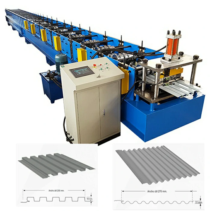
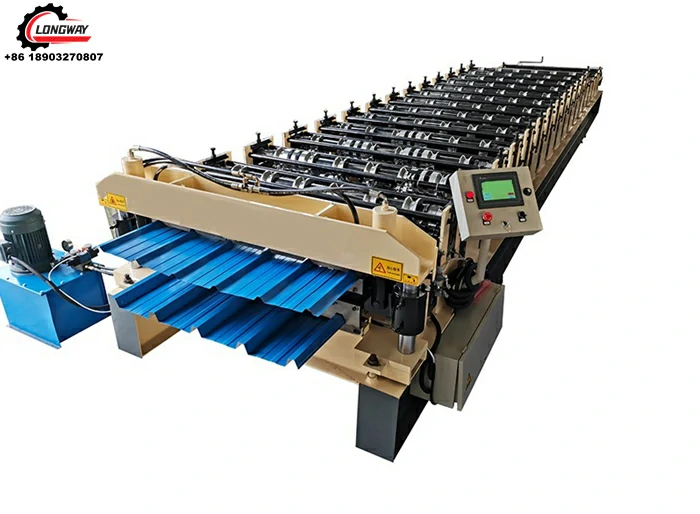
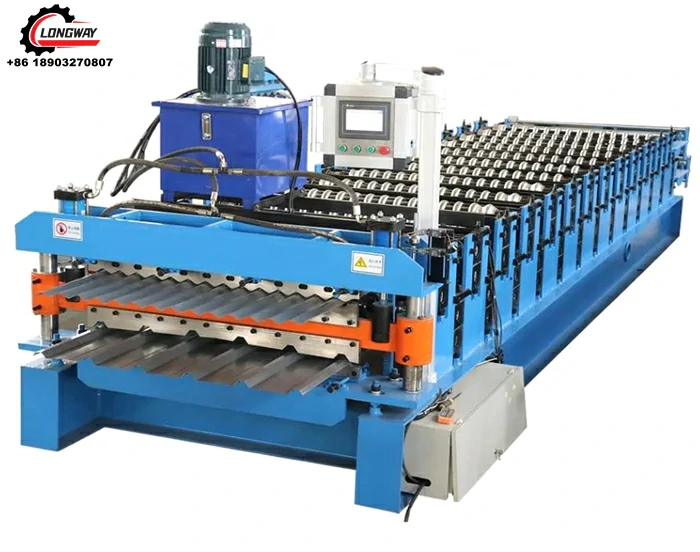
Talk about Roll forming-Roll Forming Machine
A variety of cross-section profiles can be produced, but each profile requires a carefully crafted set of roll tools. Design of the rolls starts with a flower pattern, which is the sequence of profile cross-sections, one profile for each stand of rolls. The roll contours are then derived from the flower pattern profiles. Because of the high cost of the roll sets, computer simulation is often used to develop or validate the roll designs and optimize the forming process to minimize the number of stands and material stresses in the final product.
Roll-formed sections may have advantages over extrusions of a similar shapes. Roll formed parts may be much lighter, with thinner walls possible than in the extrusion process, and stronger, having been work hardened in a cold state. Parts can be made having a finish or already painted. In addition, the roll forming process is more rapid and takes less energy than extrusion.[1][2]
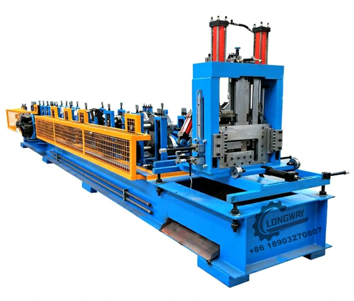
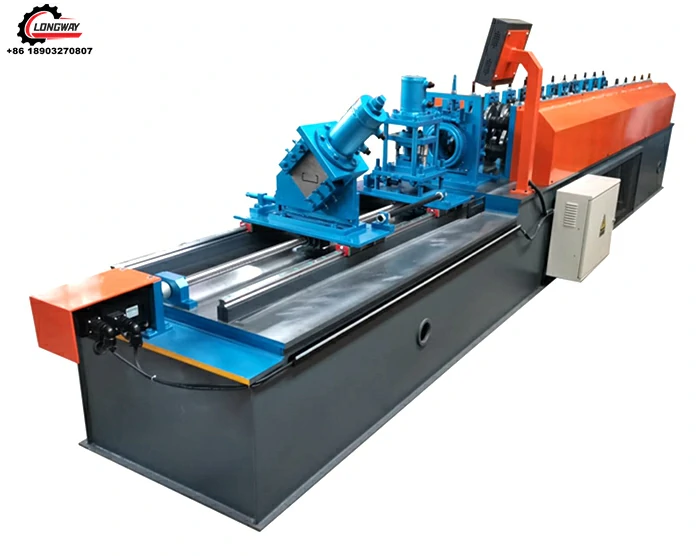
Roll forming machines are available that produce shapes of different sizes and material thicknesses using the same rolls. Variations in size are achieved by making the distances between the rolls variable by manual adjustment or computerized controls, allowing for rapid changeover. These specialized mills are prevalent in the light gauge framing industry where metal studs and tracks of standardized profiles and thicknesses are used. For example, a single mill may be able to produce metal studs of different web (e.g. 3-5/8" to 14 inches), flange (e.g. 1-3/8" to 2-1/2") and lip (e.g. 3/8" to 5/8") dimensions, from different gauges (e.g. 20 to 12 GA) of galvanized steel sheet.
Roll forming lines can be set up with multiple configurations to punch and cut off parts in a continuous operation. For cutting a part to length, the lines can be set up to use a pre-cut die where a single blank runs through the roll mill, or a post-cut die where the profile is cut off after the roll forming process. Features may be added in a hole, notch, embossment, or shear form by punching in a roll forming line. These part features can be done in a pre-punch application (before roll forming starts), in a mid-line punching application (in the middle of a roll forming line/process) or a post punching application (after roll forming is done). Some roll forming lines incorporate only one of the above punch or cut off applications, others incorporate some or all of the applications in one line.
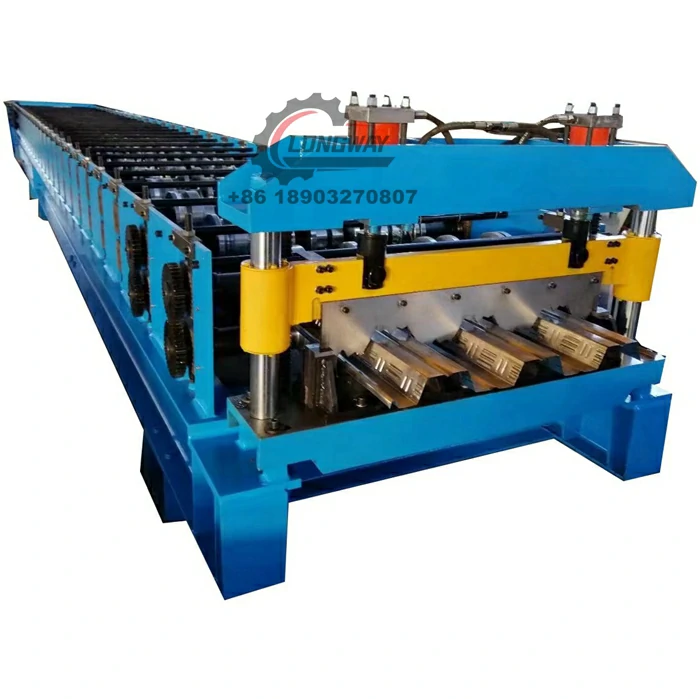
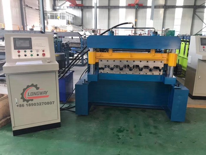
Steel deck floor roll forming machine
Process[edit]
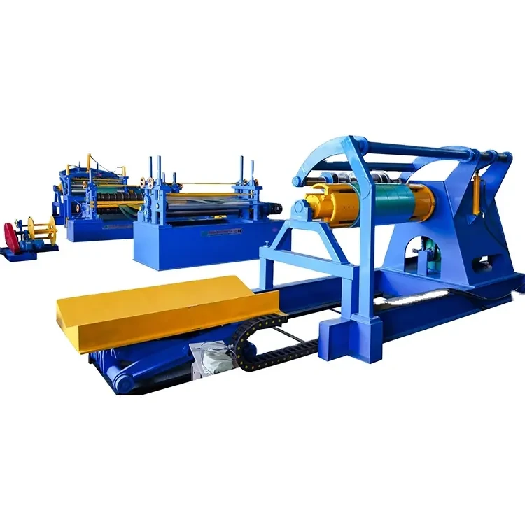
Roll forming is, among the manufacturing processes, one of the simplest. It typically begins with a large coil of sheet metal, between 1 inch (2.5 cm) and 20 inches (51 cm) in width, and 0.004 inches (0.10 mm) and 0.125 inches (3.2 mm) thick, supported on an uncoiler. The strip is fed through an entry guide to properly align the material as it passes through the rolls of the mill, each set of rolls forming a bend until the material reaches its desired shape. Roll sets are typically mounted one over the other on a pair of horizontal parallel shafts supported by a stand(s). Side rolls and cluster rolls may also be used to provide greater precision and flexibility and to limit stresses on the material. The shaped strips can be cut to length ahead of a roll forming mill, between mills, or at the end of the roll forming line.
Geometric possibilities[edit]
The geometric possibilities can be very broad and even include enclosed shapes as long as the cross-section is uniform. Typical sheet thicknesses range from 0.004 inches (0.10 mm) to 0.125 inches (3.2 mm), but they can exceed that. Length is almost unaffected by the rolling process. The part widths typically are not smaller than 1 inch (2.5 cm) however they can exceed 20 inches (51 cm). The primary limitation is profile depth, which is generally limited to less than 4 inches (10 cm) and rarely larger than 6 inches (15 cm) due to roll-imparted stresses and surface speed differentials that increase with depth.
- Tolerances can typically be held within ±0.015 inches (0.38 mm) for the width of the cross-sectional form, and ±0.060 inches (1.5 mm) for its depth.[3]
Production rates[edit]
The production rate depends greatly on the material thickness and the bend radius; it is however also affected by the number of required stations or steps. For bend radii of 50 times the material thickness of a low carbon steel 0.7 inches (18 mm) thick can range from 85 feet per minute (26 m/min) through eight stations to 55 feet per minute (17 m/min) through 12 stations or 50 feet per minute (15 m/min) through 22 stations.
The time for one product to take shape can be represented by a simple function: t = (L + n⋅d) / V, where L is the length of the piece being formed, n is the number of forming stands, d is the distance between stands, and V is the velocity of the strip through the rolls.[3]
In general, roll forming lines can run from 5 to 500 feet per minute (1.5 to 152.4 m/min) or higher, depending on the application. In some cases the limiting factor is the punching or cut-off applications.
Other considerations[edit]
While dealing with manufacturing, Things to consider are, for example, lubrication, the effect of the process on material properties, cost, and of course safety.
Lubrication provides an essential barrier between the roll dies and the work-piece surface. It helps reducing the tool wear and allows things to move along faster. This table shows the different kinds of lubricants, their application, and the ideal metals to use them on.
| Work material | Roll lubricants | Application |
|---|---|---|
| Nonferrous | Chlorinated oils or waxes, mineral oils | Spray, wiping roller |
| Ferrous | Water-soluble oils | Wiping, drip, spray |
| Stainless steels | Chlorinated oils or waxes | Wiping roller |
| Polished surfaces | Plastic film | Calendaring, covering, spraying |
| Pre-coated materials | Film or forced air |
The effects of the process on the material's properties are minimal.[clarification needed] The physical and chemical properties virtually don't change, but the process may cause work-hardening, micro-cracks, or thinning at bends when discussing the mechanical properties of the material.
The cost of roll forming is relatively low. When calculating the cost of the process things such as setup time, equipment and tool costs, load/unload time, direct labor rate, overhead rate, and the amortization of equipment and tooling must be considered.
Safety is also a bit of an issue with this process. The main hazards that need to be taken into consideration are dealing with moving work-pieces (up to 800 feet per minute (240 m/min)), high pressure rolls, or sharp, sheared metal edges.[3]
-
Roof Panel Machines: Buying Guide, Types, and PricingNewsJul.04, 2025
-
Purlin Machines: Types, Features, and Pricing GuideNewsJul.04, 2025
-
Metal Embossing Machines: Types, Applications, and Buying GuideNewsJul.04, 2025
-
Gutter Machines: Features, Types, and Cost BreakdownNewsJul.04, 2025
-
Cut to Length Line: Overview, Equipment, and Buying GuideNewsJul.04, 2025
-
Auto Stacker: Features, Applications, and Cost BreakdownNewsJul.04, 2025
-
Top Drywall Profile Machine Models for SaleNewsJun.05, 2025

